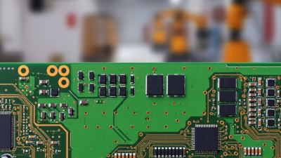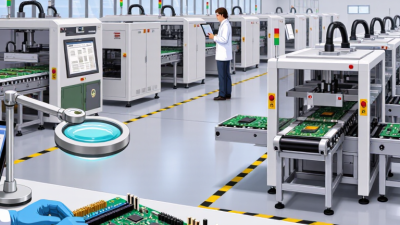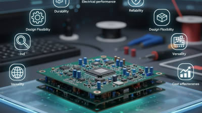
When you open a laptop, router, or medical monitor, you may see a green board covered with tiny parts. That board is not decoration. It is the working surface that connects electronic components and directs electrical signals. A circuit board gives electricity a controlled path. Without it, modern devices would need a confusing bundle of loose wires.
A circuit board usually contains copper traces, insulating layers, connection points, and mounted components. Resistors limit current. Capacitors store and release electrical energy. Integrated circuits process information. Connectors link the board to batteries, screens, sensors, or other boards. Together, these parts create a functional electrical system. It can feel almost like a miniature city. Traces act like roads, while components perform specialized jobs.
The basic idea sounds simple, but real boards are more complicated. Trace width, heat, signal speed, and manufacturing quality can affect performance. A small crack may interrupt power. Poor soldering can create an intermittent fault that disappears during testing. That is why technicians inspect boards visually, measure voltage, and compare readings with technical documents. A green board is not always a high-quality board.
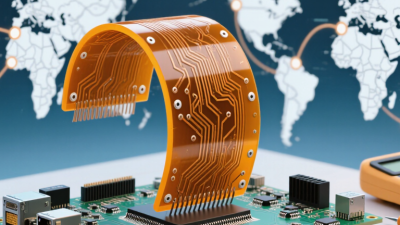
This article will explain what a circuit board is, how it works, and why its layout matters. It will follow electricity from an input connector through traces and components to an output device. You will also see how printed circuit boards differ from flexible and multilayer designs. The explanation will remain practical, while recognizing one limitation: no single board represents every electronic system. Their materials, structures, and functions can vary widely.
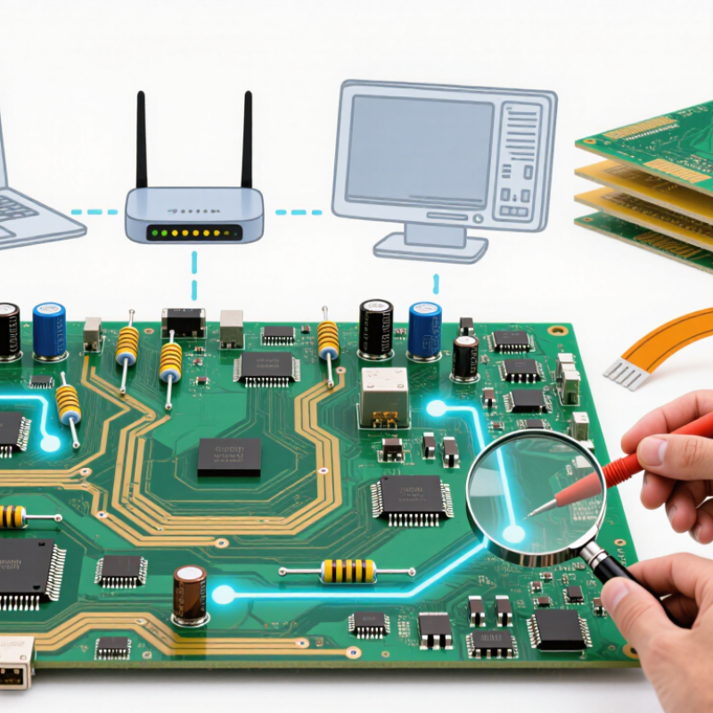
A circuit board is the physical platform that connects electronic parts. It is usually made from fiberglass, resin, copper foil, and protective solder mask. Copper traces act like narrow roads for electrical signals. Vias connect different copper layers through tiny drilled holes. Pads hold components in place, while the board’s layout controls current flow, heat, and signal timing.
A board does not think by itself. It carries instructions between parts such as processors, sensors, memory, and power circuits. When electricity enters, copper paths guide it to the correct component. The component then changes, stores, measures, or transfers that energy. IPC-2221 provides widely used design guidance for printed boards. IPC-A-600 also defines acceptance conditions for board quality. These standards matter because a small crack or weak solder joint can stop an entire device. Grand View Research estimated the global printed circuit board market at about 89.7 billion US dollars in 2023, showing the board’s continuing industrial importance. However, market figures vary by research method. They deserve careful comparison.
Tips: Check the board edge, solder joints, and connector pins under bright light. Look for discoloration, lifted pads, or broken traces. A multimeter can confirm continuity, but visual inspection should come first. Keep that habit. Even experienced technicians can miss heat damage near power components. Designing a board is partly calculation and partly disciplined observation.
| Dimension | Typical Data | How It Works or Why It Matters |
|---|---|---|
| Basic Definition | A circuit board is an insulating board with conductive copper pathways and mounted electronic components. | It mechanically supports components and electrically connects them according to a circuit design. |
| Common Board Type | Printed circuit board (PCB) | A PCB uses patterned copper traces instead of separate wires for most electrical connections. |
| Substrate Material | Glass-reinforced epoxy laminate is widely used; flexible boards use polymer films. | The substrate provides electrical insulation, structural support, and dimensional stability. |
| Conductive Material | Copper | Copper traces carry power and signals between components because copper has high electrical conductivity. |
| Typical Layer Count | 1, 2, or multiple copper layers | Additional layers provide more routing space and can create dedicated power or ground planes. |
| Copper Trace | A flat, patterned copper conductor | Trace width, thickness, and length influence current capacity, resistance, heat generation, and signal performance. |
| Via | A plated hole or vertical interconnection between copper layers | Vias allow signals and power to move between different layers of a multilayer board. |
| Component Mounting | Through-hole or surface-mount technology | Through-hole leads pass through drilled holes, while surface-mount parts are soldered directly onto board pads. |
| Solder Mask | A protective polymer coating over most copper areas | It helps prevent accidental solder bridges, protects copper from oxidation, and improves electrical insulation. |
| Component Labels | Silkscreen markings, reference designators, polarity symbols, and test points | Labels support assembly, inspection, troubleshooting, and maintenance. |
| Power Distribution | Power traces, copper planes, and ground connections | These structures deliver voltage and current while providing a controlled return path for electrical signals. |
| Signal Transmission | Electrical signals travel through traces, vias, pads, and component leads. | The routed connections determine how analog, digital, clock, and high-speed signals reach their destinations. |
| Passive Components | Resistors, capacitors, and inductors | They control current and voltage, filter noise, store energy, and shape signal behavior. |
| Active Components | Integrated circuits, transistors, diodes, and microcontrollers | Active devices amplify, switch, process, regulate, or generate electrical signals. |
| Thermal Management | Copper areas, thermal vias, heat sinks, and airflow | These methods transfer heat away from components and help keep operating temperatures within safe limits. |
| Electrical Testing | Continuity, isolation, functional, and automated inspection tests | Testing verifies that connections are complete, unintended shorts are absent, and the assembled board operates correctly. |
| Overall Function | Connect, control, distribute, and protect electronic functions | A circuit board integrates electrical pathways and components into a compact, repeatable electronic system. |